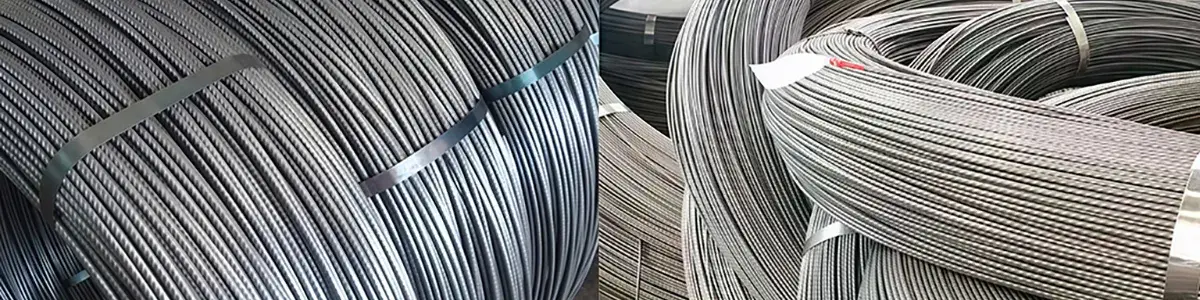
PC Wire Production Line (Prestressed Concrete Steel Wire Machine)
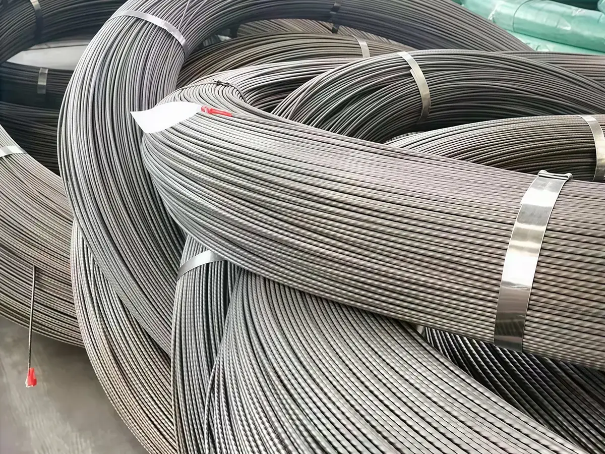
PC wire production lines, or simply PC wire lines, are engineered for the automated manufacturing of pre-stressed concrete wire, delivering a sophisticated solution for the modern pre-stressed concrete and structural reinforcement industries. Specifically designed to process high-carbon steel wire rods with a carbon content of 0.77%–0.97%, this PC wire line ensures the output meets the most demanding structural integrity standards.
This pre-stressed concrete steel wire production line integrates mechanical, electrical, and hydraulic systems into a seamless, automated wire processing flow. It is capable of handling an inlet diameter range of 8mm to 13mm, transforming high-carbon steel wire rods into PC wire with outlet diameters from 3mm to 10mm, providing high tensile strength and low relaxation characteristics.
Whether you are establishing a new steel wire processing facility or upgrading an existing PC wire manufacturing plant, our PC wire production line can meet your rigorous requirements of precision-controlled stabilization treatment and high-speed drawing processes.
| Raw Material | High-carbon steel wire (Carbon Content: 0.77%–0.97%) |
Input Wire Diameter | 8–13 mm |
| Output Wire Diameter | 3–10 mm | Finished Tensile Strength | 1570–2300 MPa |
| Spool Diameter | Ø1200 mm | Production speed |
Ø3–Ø4 mm: 170–180 m/min Ø5–Ø8 mm: 150 m/min Ø9–Ø10 mm: 120 m/min |
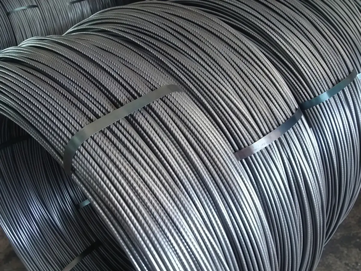
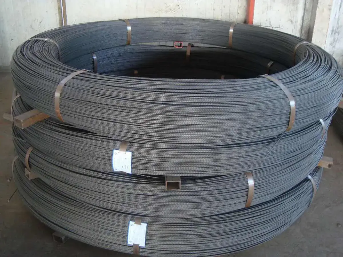
| Product Types | Plain, indented, spiral |
Wire rod coil → Wire rod payoff stand → Horizontal/vertical wire drawing machine → Straightening unit for plain / Spiral/indented PC wire → Medium-frequency induction heating furnace → Water cooling trough → Tension capstan → Auxiliary capstan → Hydraulic shear → Large take-up spool
-
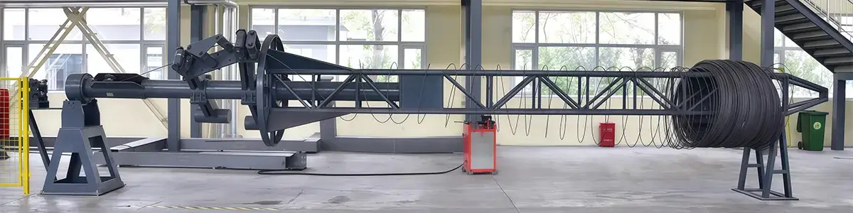
- Dimensions: Ø900 mm × 7000 mm
- Compressed Air Pressure: 500–700 kPa
- The guide rod is induction hardened to support smoother wire rod movement during pay-off.
- A rotating arm unwinds the coil in reverse, and the first drawing pass pulls the wire out through the guide pulley.
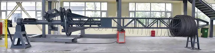 Wire Rod Payoff Stand
 -
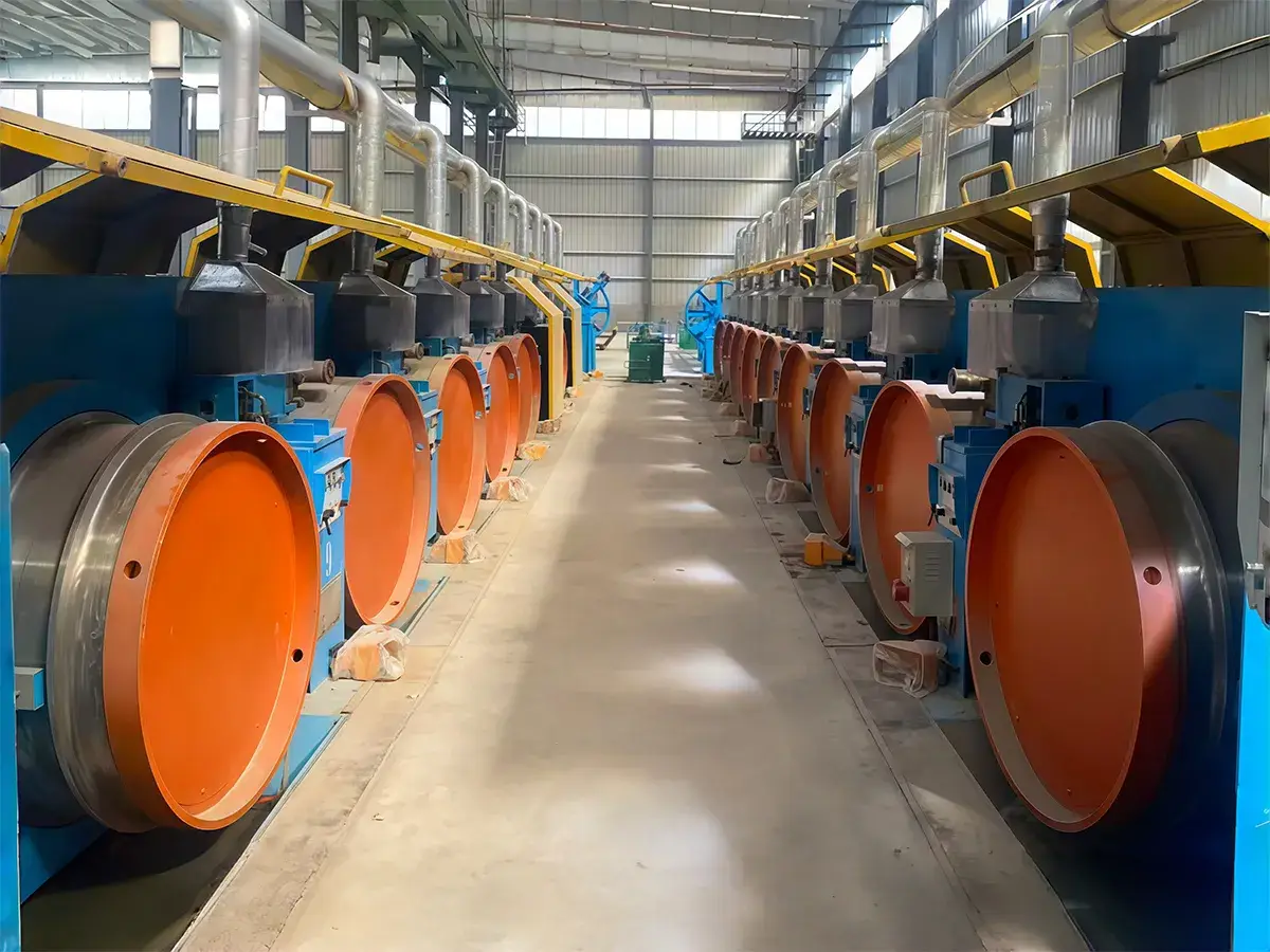
- Each drawing machine is mounted on an independent frame.
- The reducer has a cylindrical gear transmission and a hardened gear surface, which helps keep operation steady and noise below 80 dB. Larger gearboxes are fitted on the first three drawing passes, and the reducer is covered by a one-year warranty.
- Made from 42CrMo ring-forged steel, the capstan is surface hardened on the rounded corners and tapered areas, then ground for a smoother finish. The hardening depth is 2–4 mm and working surface hardness reaches HRC ≥ 60.
- The capstan surface is designed to guide the wire more smoothly during winding, so the wire does not jump, cross over, or press against adjacent loops. A wire accumulation height of at least 350 mm also helps improve cooling while the wire is running on the capstan. The capstan is connected to the main shaft by key connection, and the shaft uses a tapered design. During normal operation, the tuning roller runs steadily and only moves slightly when speed is adjusted. The capstan wall is 20 mm thick, and the structure uses a detachable water jacket.
- The capstan uses both internal water cooling and external ring-type air cooling. Air cooling power is 2.2 kW. Inside the capstan, the cooling water jacket uses a narrow-slot design. A labyrinth structure is used between the capstan and its seat to keep lubricant dust from entering the inner cavity, which helps avoid circulating water contamination and blockage in the return pipe.
- Water enters and exits through a pressure-type hollow shaft. The inlet connection is G1, while the return system uses four inlet and four outlet lines, all fitted with 3/4 aluminum-plastic pipes. Internal water cooling is arranged in two layers with lower inlet and upper outlet flow. The lower layer is narrower, while the upper layer is wider.
- Closed direct-immersion water cooling is used for the drawing dies. Flexible hoses connect all die boxes to the corresponding water supply pipes. Separate valves are provided on the operating side for die box water supply, float indicators show the flow rate, and all joints use quick connectors.
- To ensure proper cooling performance, the PC wire production line requires water that meets municipal supply standards, with a pressure of 0.2–0.35 MPa, an Ø80 inlet, an Ø200 return, and flow of 50 m³/h.
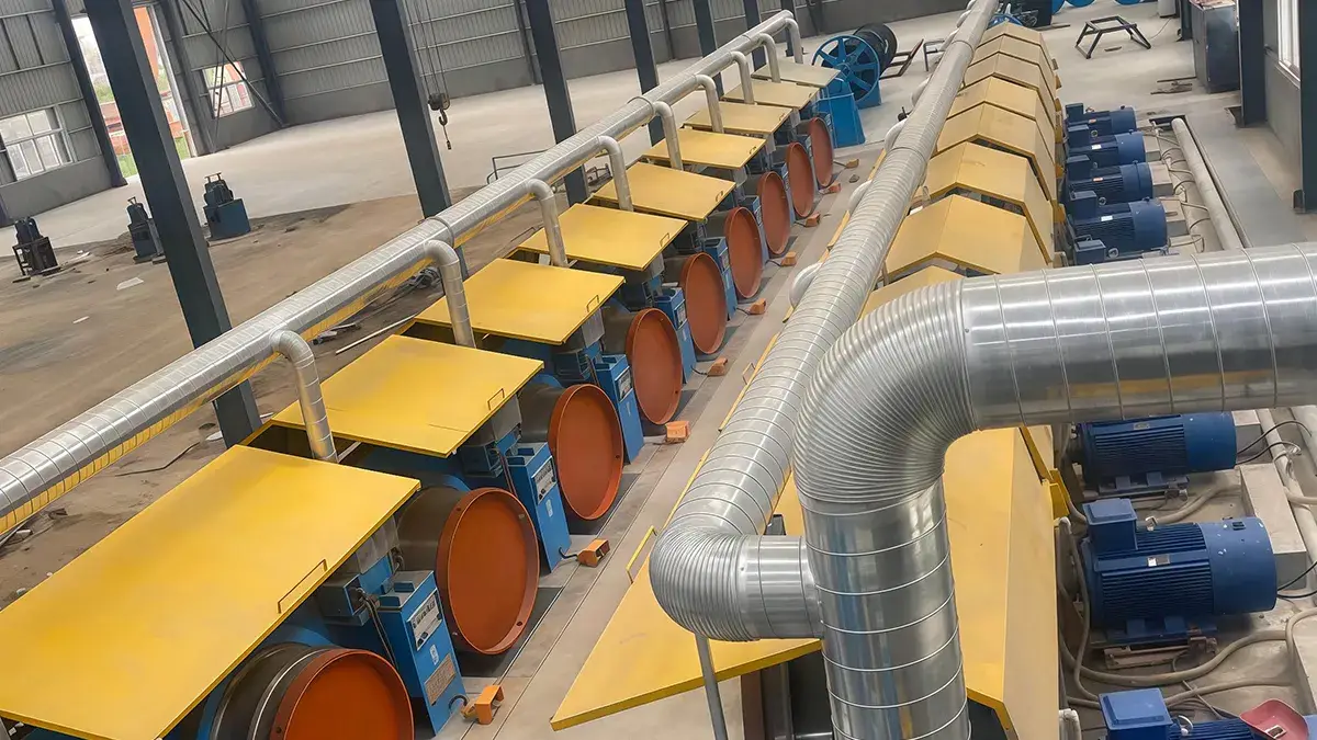
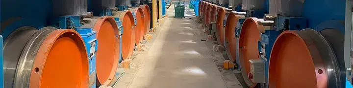 Wire Drawing Machine
 -
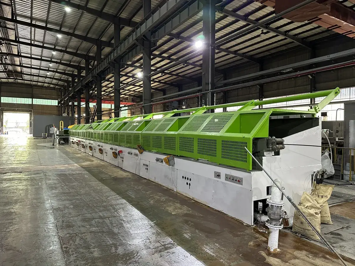
Cooling Trough
The cooling trough sprays water onto the wire at an appropriate angle for more effective cooling. Water temperature inside the trough is monitored by a temperature sensor and shown on the display screen, while a variable-frequency pump adjusts water flow as needed to keep the cooling water temperature at no more than 40°C. The trough is 7 m long, and the outlet is fitted with an air wipe to dry the wire after cooling. Both manual and automatic control are available, and the cooling water is recirculated through the cooling circuit.
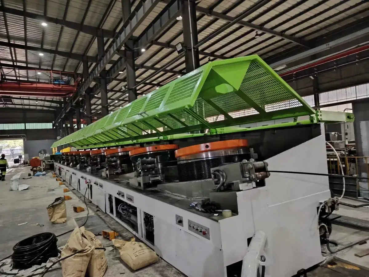
-
- Diameter: 3200 mm
- Quantity: 1
- Surface Hardness after Induction Hardening: 56–60 HRC
- Maximum Tension: 3000 kg
Tension Wheel -
- Max. Outer Diameter: 2800 mm
- Min. Inner Diameter: 1200 mm
- Max. Load: 2500 kg
- Number of Baskets: 2
Vertical Take-Up Unit (Basket Type)